To the -> Shop!
Short description
Expands the Minimal-X Adapter Boards I2C, SPI, UART and 1-Wire with further header connectors – readily accessible as header pins/plugs.
Minimal-X Extension Board is extending the Minimal-X Adapter Board for
- TTGO
- Heltec WiFi Lora 32
- Heltec Cube Cell
- DOIT ESP32 DevKitV1 (30 pin)
Problem: You would like to connect more than one sensor to I2C, SPI, UART and/or 1-Wire.
Solution: Extend the development board with this extension board where a multiplication of sensors is easy. See features below.
Software: Free software examples on Github: https://github.com/itofficeeu/
Features (Version LeA_v4)
- 6 x I2C connector
- 10 x 1-Wire connector
- 1+2 x SPI connector
- 1 x UART connector in 2 configurations with 1 x TXRX / 1 x RXTX
- 1+1 x analogue connector
- +4 x analogue connector via ADS1115/ADS1110 and I2C.
- ADS1115 can be connected with a jumper to either 3.3V or 5V, as you like.
- space for a button. combined with jumpers for different adaptable configurations.
- space for a LED and header-“plug”.
The first analog connector is directly connected to the voltage divider on the adapter board. So it will use the voltage divider implemented on the adapter board.
The first SPI connector is directly connected to wiring on the adapter board. So it will follow the wiring made on the adapter board.
To the -> Shop!
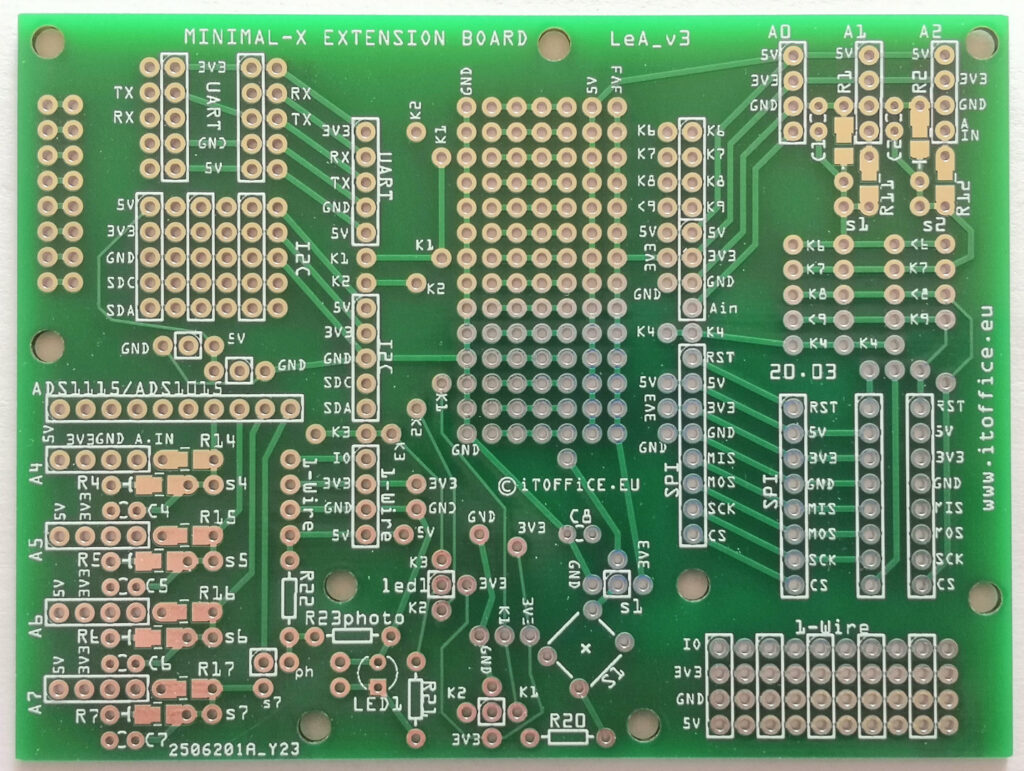
Features (Version LeA_v3)
- 6 x I2C connector
- 10 x 1-Wire connector
- 1+2 x SPI connector
- 1 x UART connector in 2 configurations with 1 x TXRX / 1 x RXTX
- 1+2 x analogue connector
- +4 x analogue connector via ADS1115/ADS1110
- ADS1115 is connected to “5V” supply – could end up being 5.2V also. NOTE: Some MCUs do not supply 5V Vcc out.
- space for a button. combined with jumpers for different adaptable configurations.
- space for a LED and header-“plug”.
The first analog connector is directly connected to the voltage divider on the adapter board. So it will use the voltage divider implemented on the adapter board.
The first SPI connector is directly connected to wiring on the adapter board. So it will follow the wiring made on the adapter board.
Top:
Example of an resistor plan for ADS1115 connected to 5V power supply:
R14 = 0 kΩ
R4 = not connected
R14+R4 = not applicable
Analog in = 5.00 V max / current usage of microcontroller pin only
R15 = 33 kΩ
R5 = 33 kΩ
R15+R5 = 66 kΩ
Analog in = 10.00 V max / 0.15 mA max + current usage of microcontroller pin
R16 = 22 kΩ
R6 = 3 kΩ
R16+R6 = 25 kΩ
Analog in = 41 V max / 1.67 mA max + current usage of microcontroller pin
R17 = 47 kΩ
R7 = 3 kΩ
R17+R7 = 50 kΩ
Analog in = 83 V max / 1.60 mA max + current usage of microcontroller pin
NOTE: Some MCUs do not supply 5V Vcc out.
To the -> Shop!
Features (Version LeA_v1)
- 12 x I2C connector
- 10 x 1-Wire connector
- 4 x SPI connector
- 1 x UART connector
- 3 x analogue connector
- +4 x analogue connector via ADS1115/ADS1110
- ADS1115 is connected to “3.3V” supply
Top:

Example of an resistor plan for ADS1115 connected to 3.3V power supply:
R14 = 0 kΩ
R4 = not connected
R14+R4 = not applicable
Analog in = 3.3 V max / current usage of microcontroller pin only
R15 = 33 kΩ
R5 = 33 kΩ
R15+R5 = 66 kΩ
Analog in = 6.6 V max / 0.10 mA max + current usage of microcontroller pin
R16 = 22 kΩ
R6 = 3 kΩ
R16+R6 = 25 kΩ
Analog in = 27.500 V max / 1.10 mA max + current usage of microcontroller pin
R17 = 20 kΩ
R7 = 1 kΩ
R17+R7 = 21 kΩ
Analog in = 69.3 V max / 3.30 mA max + current usage of microcontroller pin